
G67bg 5 Wiring Diagram
Ignition control replacement parts must be used only for field replacement of existing equipment as listed above. Check the wiring diagram furnished by the appliance manufacturer, if available, and compare with tables 5 through 8.

2 Humbucker Wiring Diagram Regular 5 Way Switch Database Wiring Diagram Sample
After 5 minute delay, a new trial for ignition is initiated.
G67bg 5 wiring diagram. All of the wires are connected to the ignition controller at the factory except to the th terminal. After 5 minute delay, a new trial for ignition is initiated. And wiring diagrams for series g60, g65, g66, g67, g770, and csa's important:
If you run into an electrical problem with your gmc, you may want to take a moment and check a few things out for yourself. When i turned it on nothing happened. I tried bypassing the thermostat still nothing.
4.13w x 4.13h x 1.5d electrical rating input 18 to 30 vac, 25 vac nominal max. If the unit has terminal block wiring, cut and strip the ends as needed. The controls and wiring from water or steam flow.
Refer to the wiring diagram label (or the appropriate diagram on page 3) and connect the wires. Wiring diagram for g67b( )! Refer to the wiring diagram label (or the appropriate diagram on page 3) and connect the wires.
Printing on 8.5 x 11 paper; Terminals 1 and 2 on the g67 are tied together internally. Carefully follow any special instructions affecting the general procedures outlined below.
Protect (cover) the controls and wiring from water or steam flow. Boards comes with wiring instructi These replacement parts must not be used for new field applications.
Terminals 1 and 2 on the g67 are tied together internally. Is this the most likely the problem and if so how do i go about checking it ? 5 6 mv pv limits in the thermostat line only 24 vac power supply pilot burner ground ground terminals flame sensor high voltage cable install the jumper supplied with the replacement control between terminals 2 and 6.
All wiring should be in accordance with the national electrical code (nec) and all other local codes and If the unit has terminal block wiring, cut and strip the ends as needed. Disconnect the power supply before making wiring connections to prevent electrical shock or equipment.
Wiring diagram for g67b( ) 56 2.21 50.8 2.00 8.89 0.35 5. 5 < y75 flame sensor thermostat power supply 24 vac 1 2 4 3 high voltage cable high limits in this line only jumper pilot burner ground ground terminals mv pv 5 power is wired directly to r (common) on the thermostat. There are two loose wire assemblies in the kit.
Before when i turned it on it made a click and the burner would come on. This is a brand new honeywell intermittent pilot gas ignition control board module. 5 power is wired directly to r (common) on the thermostat.
Meets all codes requiring dual valve safety shutoff. All of the wires are connected to the ignition controller at the factory except to the th terminal. There are two loose wire assemblies in the kit.
After opening the pdf file, you can click on the printer icon in the acrobat reader toolbar and make sure to check the box for 'shrink oversized pages to paper size.' wiring diagrams for all new products are regularly added to our web site. • installs easier with wiring connections, manual selector and adjustments on top of valve. Refer to figure 2 through figure 5 for wiring diagrams.
He or she should have a thorough understanding of electricity, reading wiring diagrams and the work to be performed. Mount the controls high enough above the Avoid personal injury or property damage by making sure the control functions properly and there are no gas leaks.
Get notified on new and inbound inventory. ${ getproductid() } mfg #: In no way shall north america hvac be liable for any loss, damage, injury, including any incidental or consequential damages, or death as a.
${ product.model } subscribe to johnson controls. Follow this checkout and startup.
Ibanez Wiring Diagram 3, Switch Professional Ibanez Wiring Diagram 3, Switch Free Download

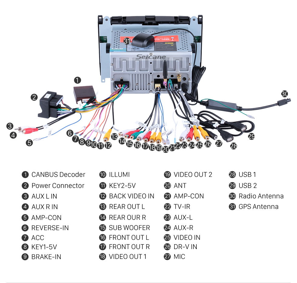
Assistance with COMAND 2.5 Wiring for Aftermarket Stereo Forums

Ibanez 2 Humbucker 5Way Switching Wiring Making & Modding Discussions on theFretBoard

5 Pin Relay Wiring Diagram Driving Lights — UNTPIKAPPS

I need a wiring diagram for a 2008 Chevy Silverado I'm trying to figure out which wire is the

Having an issue with my Volvo Penta 5.7 Cranks but won't start... Replaced the Stater and the
Relay Diagram 5 Pin — UNTPIKAPPS

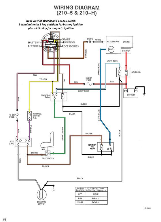
Toro Wheelhorse 2105 wiring diagram Wheel Horse Electrical RedSquare Wheel Horse Forum
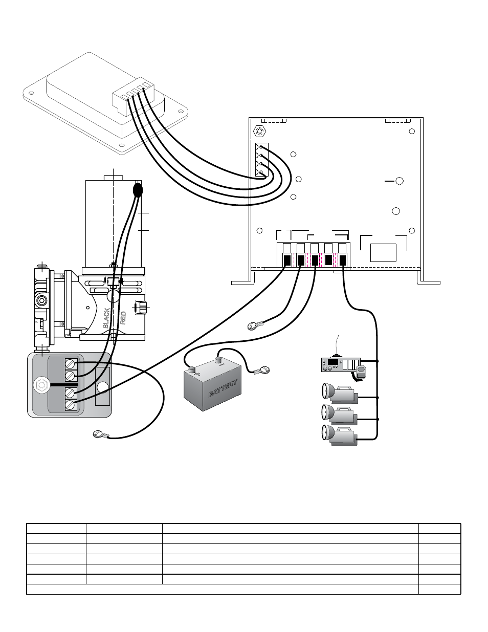
Pump plus, Installation wiring diagram, Wire size chart Kussmaul Electronics 09191000 User

12V 5 Pin Relay Wiring Diagram deltagenerali.me Wiring diagram, Light switch wiring
Warwick Rockbass Streamer Wiring Diagram Wiring Diagram
[QUESTION] HSH wiring with a 5 way switch, 1 vol, 1 push pull tone Guitar

5 7 Mercruiser Starter Wiring Diagram Wiring Diagrams • intended for Mercruiser Ignition
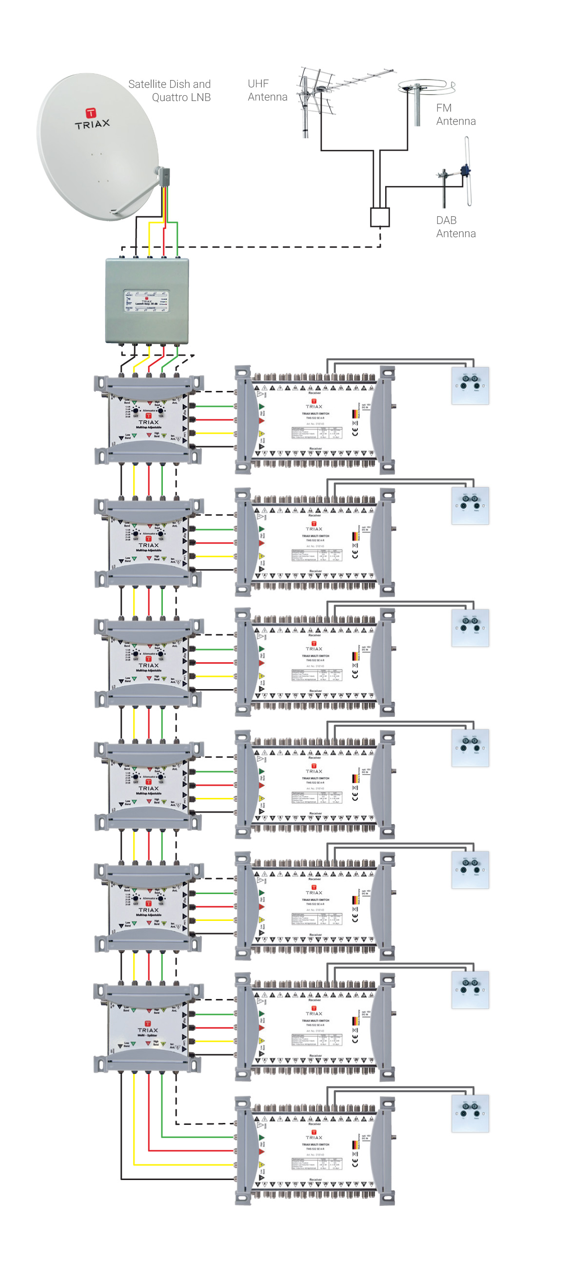
Wiring Diagram For Multiswitch
Are there better wiring diagrams available for a 5 way rotary switch? Official PRS Guitars Forum


5 Prong Relay Wiring Diagram

OEM Johnson Controls Carrier Bryant Furnace Control Board G67BG3 LH33EP040 eBay

I need engine wiring diagram for a 2003 Ram 1500 4.7L CA emissions. in particular the crank

5 Way Switch Wiring Diagram — UNTPIKAPPS
