Nes Controller Wiring Diagram
Asked nov 2 '09 at 4:18. Looking at the arkanoid paddle info from the nesdev wiki you'll see it uses d3 for the button and d4 for the knob.
technologies 4x SNES and/or NES controllers to USB adapter circuit
Use a known good controller.

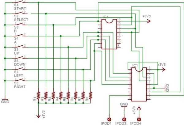
Nes controller wiring diagram. The snes controllers drive data for the first button at the falling edge of latch. There are tutorials out there for using an nes controller with an arduino, but helpful schematics can be found here. This is where almost all problems occur.
Data for all other buttons is driven at the rising edge of clock. I searched around but can't seem to find any wiring diagrams for this 4 wire. 3d case files were designed by dinierto designs and are available on thingiverse.
Should be pretty easy to do, because the wire can just be pushed into the nes controller for prototyping. Gamecube games on gamecube gamecube games on wii wii virtual console games raphnet.net n64/gc to usb adapter. Learn to solder correctly and use the right controller for the chip.
If you are interested let me know and i can draw up a laymen (read shitty) diagram to the wiring. All in all it was really basic. Does anyone have a pinout diagram for the nintendo nes controller?
Along with info and diagrams showing how to wire a nes controller to your gameboy. Follow edited sep 2 '17 at 20:47. Based on daemonbite retro controllers by combining the nes/snes and genesis projects together for a specific wiring layout to support 3 different controllers with a single arduino pro micro.
Images december 22, 2019 post a comment. 1.3) supported consoles at the moment, the adapter is known to work on the following setups: Make sure they get pushed in all of the way though.
This means that it's better to use 5 volts for a logic 1 when driving the controller's clock and latch pins. I'd like to connect the nes controller to an arduino. (as i dont have the official controller specifications, i cannot know for sure what is the voltage threshold for a logic 1.
Only 4 of the 16 clock cycles are shown for brevity. If you'd like a kit for this version please let us know! Can be installed inside a controller for a permanent conversion or used to build a custom adapter.
Hopefully the following timing diagram will serve to illustrate this. The data signal from the controller is at 5 volts when high. Alps r22 / france rgb nes.
After latching the 4 controllers button states simultaneously using the 'latch' line, controllers 1 and 2 are read serially. The nintendo 64 controller wire wrap according the diagram on the right.n64 controller wiring diagram ~ here you are at our site, this is images about n64 controller wiring diagram posted by alice ferreira in diagram category on nov 12, you can also find other images like wiring diagram, parts diagram, replacement parts. The length of the cables on each controller is very short.
The wiring for every generic n64 controller i've found thus far. Use an arduino with an n64 controller: Pcb kits + assembled units available on tindie.
Nes/snes/n64/gamecube controller to wiimote circuit a small circuit to connect a nes, snes, n64 or gamecube controller to a wiimote. Snes and nes controllers work at 5 volts. The retrokit is only designed for one controller.
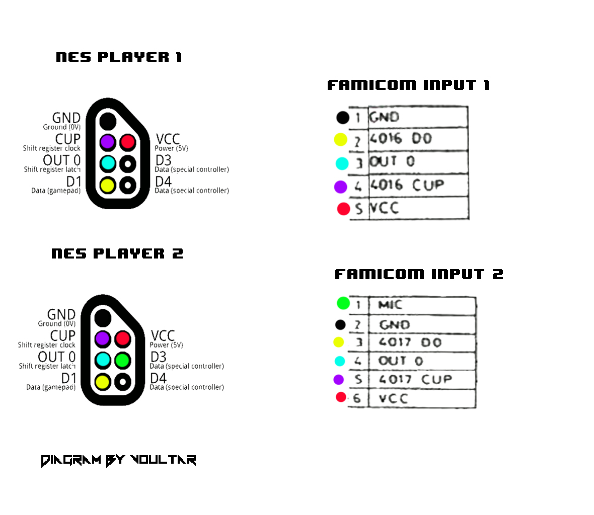
Then the nes sends a series of eight low pulses down the clk line, which makes the controller shuffle bits (one for each clk pulse) down. Here is the nes controller port pinout copied from the nesdev wiki: This operation is then repeated, but with select in a different state to access controllers 3 and 4.
This post has board scans of both the front lcd, and back cartridge pcbs. Nes controller to famicom adapter. 7,027 1 1 gold badge 22 22 silver badges 39 39 bronze badges.
Controllers that do not work on the original system will not work with the retrokit. Maybe we can take an educated guess. This is the general pin layout for the nes controller, along with the fritzing wiring diagram.
Nes controller to xbox mod will show you how to prepare the nes controller for use on the xbox. Mobility aids scrubbers personnel carriers small walkers bd4 curtis dc motor controller wiring diagram epanel highq 1228 2908 24v 110a speed controller for mobility scooter new curtis 1510 controller wiring diagram wiring diagram third volt meter wiring. This page has a schematic of the paddle controller.
It shows the traces to dan215 that outputs the signals to the cpu, and the. Here is a multitap pinout diagram including mcu pin names for wiring: (work in progress) with the help of @seerofvoid420 we made this diagram of the front button pcb inside of a dmg.
They have instructions for the wiring from there, and the only thing extra i did was add a usb hub between the controller chip and usb plug so that i could add the flash drive too. Now also compatible with the nes and snes classic editions. This is because the console was designed to be placed on the floor in front or very near the tv, with the player seated in front of the console.

Nes Controller Wiring Diagram Wiring Diagram And Schematic Diagram Images
NES Controller Interface with an Arduino UNO
30 Gamecube Controller Diagram Free Wiring Diagram Source

Nes Controller Wiring Diagram Wiring Diagram And Schematic Diagram Images
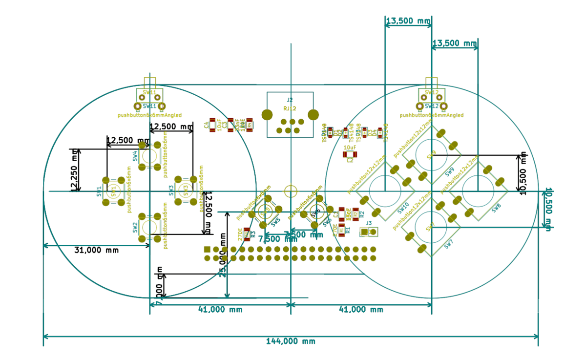
Nes Controller Wiring Diagram flilpfloppinthrough
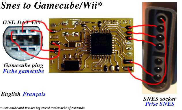
N64/Snes/Nes controller to gamecube/Wii conversion project
technologies 4x SNES and/or NES controllers to USB adapter circuit
21 Elegant Nes Controller Wiring Diagram
technologies NES/SNES/N64/Gamecube controller to Wiimote circuit

Nes Controller Wiring Diagram Wiring Diagram And Schematic Diagram Images

The Poor Student Hobbyist Wireless NES Controller Using Arduino
4 NES and/or 4 SNES controller(s) to USB
4 NES and/or 4 SNES controller(s) to USB

The Poor Student Hobbyist Wireless NES Controller Using Arduino

